- LCD Monitors[1]
- Touch Screen Monitors[1]
- Other Waterproofing Materials[2]
- Card Readers[10]
- Chargers[1]
- Earphones & Headphones[10]
- Speakers[10]
- Other Consumer Electronics[3]
- Other Electrical Equipment[1]
- Keypads & Keyboards[2]
- Other Electronic Components[2]
- Mobile Phone Bags & Cases[10]
- Other Welding Equipment[8]
- Oscilloscopes[2]
- Mobile Phone Cables[1]
- Mobile Phone Chargers[10]
- Mobile Phone Flex Cables[9]
- Mobile Phone Housings[4]
- Mobile Phone Keypads[4]
- Mobile Phone LCDs[6]
- Other Mobile Phone Accessories[10]
- Contact Person : Ms. Chuang Echo
- Company Name : Guangzhou Telesailor Electronics Ltd.
- Tel : 0086-20-22296315
- Fax : 0086-20-22296315
- Address : Guangdong,GuangZhou,liWan District
- Country/Region : China
- Zip : 510120
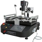
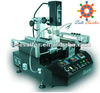
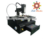
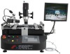
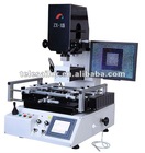
Three heating zones BGA Reworking Station of CF-280T


Related Product Searches:Three heating zones BGA Reworking Station of CF-280T,High Quality,BGA reworking station , automatic bga rework station,CF-280T
Feature of Chinafix BGA reworking machine:
1,Special design for tongs, clamp notebook’s mainboard easilier.
2,New style of Chinafix Tuyere adopts the design of transmiting flow,it can make the flow and tempreture spreads uniformlier.It adopts the laser cutting and whole-design technology, can keep the uniformity of air quantity and tempreture at any contion,thus increase the successful rate to overhaul chips. Now the added big tuyeres can support more and more chips with big size for reworking.
For the PCB with more components on bottom, turning four corner’s mandril of tuyere can surport it, as the below picture showed:
3.IR-heating board from bottom with bigger area. During the same kinds of the products, our IR-heating board’s size is the biggest.
4. The design of upper tuyere protects chips’ core better. Mesh’s diameter becomes bigger from center to edge, so make heat spread on BGA chip uniformly.
5. Due to the particularity of BGA design, there is more difference of temperature between testing postion of control tempreture and heating postion. At the same setting tempreture, using the chip of different size, BGA chip’s auctual heating tempreture is also different. Because in unit space, the more the quantity of heat, the higher the tempreture. During the design of BGA reworking machine, some products just ignore this point, so that result in lots of problems about exploding.
In all of our products, there is an Air Regulator knob, the way how to use will be introduced in the following introduction. About Air Regulator, “5” is the maximum tap position, “0” is the minmum.
Common problems about BGA Welding
1,How to regularize BGA reworking machine and choose the suitable curve?
BGA chips’ welding is affected by many external and environmental factors, such as air temperature,humidity, light air flow in room, thickness of PCB, distribution of PCB cooper, etc. There is not a kind of curve which can be used at any place or any environment to finish all soldering. According to our statistics, only 30% clients can directly use our scheduled curve without any regulation. The room temperature in our factory where we regularize the machine is 25°C.The room is half-closed and in higher air humidity.And the regularized chips are generally north bridge on mainboard of notebook.So,when this problem happened,we must regularize it according to our curve and the actual situation.
Adjustment method,use north bridge on mainboard of notebook or PC(use the waste board to adjust, but must keep PCB smooth without any shapeless and metamorphism). Suggest not to adjust with the chips of notebook’s graphic card or other samller size ones.Clamp the mainboard being soldered smoothly by tongs.Put the end of temperature measuring wire between chip and PCB,set up the parameter as our provided curve,then start welding.
First,observe the temperature measured by temperature measuring wire when finishing the fourth stage, the ideal temperature of unleaded curve is about 217°C, the one of leaded curve is about 183°C. The two figure of temperature is the meltering point of unleaded solder and lead solder. But the solder under chip still doesn’t melt, concerned about reworking,the ideal temperature of unleaded curve is about 235°C, the one of leaded curve is about 200°C,now after melting and recooling, it will reach the idealest strength.
For example of the unleaded soldering:
After finishing the fourth heating stage, the temperature still can’t reach about 217°C,then increase the temperature of the third and fourth heating stage.
Illustration:when the actual measured temperature reaches 205°C,then adjust the upper and bottom heating temperature to 10°C higher individually.If the balance is bigger,actual temperature is 195°C,suggest to increase 30°C of bottom, 20°C of upper. Upper Temperature should not be increased too higher,in case of resulting in stronger thermal shock to chip.
After heating,if the temperature of the fourth stage reaches 217°C, it’s a ideal condition; if beyond 220°C, then observe chip’s temperature before finishing the fifth stage.Lower than 245°C is suitable. If more beyond 220°C,adjust the fifth stage’s temperature lower properly.
2.When welding, the four corners of tuyere bottom always can’t hold
out against the mainboard meanwhile, what to do if some corners hold out against components?
About the bottom tuyere, we have designed corners to be screws to adjust height by turning. According to the difference of four corners, we can adjust four corners’ height flexiblly.
If some corners hold out against components, we can stagger it for 1-2mm, or turn the middle screwed mandril higher, only support PCB by the middle mandril, now the bottom temperature need be increased about 10°C.
3, What’s the function of “Air Regulator” button?
The size of our tuyere is from 28mm to 46mm, in total 5 types. Though using the same temperature setting, but different tuyere, the final heating temperature on chip also varies. The smaller the tuyere, the more the quantity of heat in a same unit, so the higher the temperature of chip. This is a very simple principle, all of welding equipments by hott air keep to this rule. When welding small chip, use the smaller tuyere, adjust the air speed lower by “Air Regulator” button, it can decrease the rate of expanding bridge.
Of course, the other method is to adjust the distance bewteen tuyere and chip properly, proper adjusting 1-2mm can also decrease the heat of chip.
1, Which problems need to notice when welding 775 CPU pedestal?
The distribution of 775 pedestal’s PCB copper foil is not very uneven, The one closed to the outboard is subduple ground wire and power-up copper foil’s distribution, the subduple PCB closed to innerboard is all singal wire. So to 775 CPU pedestal’s welding, the temperature measuring wire must be put between PCB and 775CPU pedestal, closing to outboard(mainboard joint’s direction and power-up components’ direction) when measuring temperature.
According to our measuring, the mixmum difference of temperature between 775CPU pedestal and two pieces of copper foil on PCB is 20°C, because plenty of ground wire and power-up copper emanates heat to PCB other position.
Directly welding 775 pedestal(No removing,directly reweld),must use liquid scaling powder.
When welding 775 pedestal,must take down new socket’s iron cover.
Tuyere must be suitable,choose the tuyere as same size as 775 pedestal’s plastic interior casing.
When welding, must keep 775 pedestal smooth by tongs. Don’t think it’s boring, adjust the tuyere bottom repeatedly, insure to make the PCB part of 775 pedestal smooth.
2.Choose welding paste
Recommand to use the environment friendly scaling powder( used to weld), or BGA dedicated welding paste. But notice: BGA welding paste has the limited using time, stored in higher temperature will result in invalid easily. Such as 30°C in room, sunshine projectivity,all will make it deteriorating in a week. After deteriorating, it will lose the effect of help-welding completely. Please store it in the shady and cool place.
3. The cleaning work in BGA welding
Steel mesh is suggested to clean by the dedicated washing-board water and sonicleaning. Solder used once is not advised to recycle. Once infected in some invisible dust or little welding paste, will make big trouble on next solder-distribution. Suggest to use non-dust cloth and washing-board water to clean PCB. After solder-distribution, don’t touch solder by hands, once infected in sweat or oil stain, also can result in welding’s fail.
Remmeber:Details decide success or fail..
4.The problem about chip’s exploding and how to store
When welding BGA chip,if you hear some light flip-flop sound, it may be the bridge-exploding as we called. There is no doubt that the two reason resulting in bridge-exploding: one is nonuniform air, higher temperature on some position makes bridge-exploding; the other one is chip’s interior is so damp even with some water, during welding, water vapor spills over rapidly, makes the copper foil in chip’s inerior short circuit or open circuit. These problems also exsit on PCB, too damp PCB will cause ply’s short circuit and shapeless heavily. So about the chips stored for a long time, we suggest to stoving first, BGA reworking machine can give a simple stovinging by heating chip with 165°C for about 10 minutes.The professional handing is to use drying oven on a constant temperature, about 100°C, stoving all the board and chip for above 10 hours.
Even brand new chip,if stored in room enviroment, still absorb water in air, and result in breakdown. So,suggest to purchase moistureproof oven(generally used to store medicine)to store chips.
5. How to take down the chips with glue?
If the measured temperature by temperature measuring wire on BGA chip’s bottom is 230°C,now the solder has melted.
But why still can’t take down chips by tweezers as the commone ways? Since there is glue connecting with chip, so we must take down chips with more strength. But if the solder will fall from chip? No. Because the solder on pad has melted to liquid, but glue is poured between solder,no sticking on pad,so the solder will not fall even taking down strongly.
But we must pay more attention to the laying place of temperature measuring wire’s position:
Which problems need we notice about the laying place of temperature measuring wire’s position?
The distribution of Copper foil on PCB is irregular, on chip bottom, some is singal wire, some is supple line or ground wire.
So,with same heating temperature and different working position, supple line and ground wire absorbs more heat,and filament absorbs less heat surely. In other words, at the same 250°C,when starting to heat PCB chip,the actual temperature bottom is different, for a while,the temperature will be uniform.
So,even the measured temperature is 230°C on the laying place of temperature measuring wire’s position,the temperature on other postion maybe not reach 230°C, maybe 220°C, but still above the melting point-217°C of unleaded solder. Then we can take down chips with more strength fearlessly.
Of course, when reaching 230°C, still suggest to keep for a while, then solder will not fall easiler.
Three heating zones BGA Reworking Station of CF-280T